You have learned how to use AutoCAD drawing tools. When you activate an AutoCAD drawing tool, there are two possibilities what AutoCAD will ask you: options or specifying points. Some AutoCAD tools ask your confirmation for settings before asking you for a point. You will need to define points eventually. In this tutorial, we will discuss how we can give precise input when AutoCAD asking us for a point location.
Drawing Object versus AutoCAD Scale
First, let us discuss how we should draw in your AutoCAD drawing, relevant to your scale. We draw our object in real size. If you have 5 feet length object, then draw 5 feet length line. If you have 100 cm length object, then draw it 100 cm length. I have to emphasize this because I found some people don’t work this way. They have 100 cm length object, and because they plan to plot it to 1:100 scale, they draw it 1 cm length. It’s a no-no.
We always draw the objects in their real size in CAD… any CAD applications. We only use scale for plotting purpose. We are drawing in a limitless area. Well, I know this is not true. But most CAD application can handle your design size.
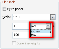
AutoCAD only has 2 units by default: inch (imperial) and mm (metric) for plotting. So we better use that two units to avoid confusion when we plot (later about this). So if you work in metric, and you want to draw 1 m length line, draw it 1000 mm.

So AutoCAD only recognize mm and inch? No. Only for plot purpose. We can use other units like feet, cm, or m, but I recommend you to use inch or mm for the first time.
‘Classic’ versus Dynamic Input
Since AutoCAD 2006 (correct me if I’m wrong) Autodesk introduce ‘dynamic input’ to AutoCAD users. If you’ve just installed AutoCAD, then this feature by default is on. If you or someone turn it off, try to turn it on. Give it a try first. Later, if you don’t like it, you may turn it off. Click the dynamic input button in drafting settings group.
![]()
The method in defining coordinate using dynamic input or ‘classic’ input is a bit different. However they have the same concept.
Relative Coordinate
Activate line tool. We will try this basic tool to comprehend how we can talk with AutoCAD about point coordinate.

AutoCAD will ask you for first point. Since we don’t have anything in our drawing yet, just click anywhere to define a start point.

Polar Coordinate
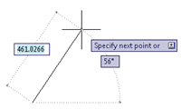
After you place the first point, AutoCAD will show you dynamic input like image below. By default the dynamic input will ask for polar coordinate input.
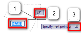
Drawing description
- The line length
- The line angle, relative to positive X axis
- The tool option

You can simply type the line length, press tab to move to angle field, type the angle value and press [enter].
When you use more complex AutoCAD tool, you probably need to change the tool options. You can press down arrow to see available options. For AutoCAD line tool, there is only ‘undo’ option. This will cancel the last line segment.
The value shown by dynamic input is relative coordinate. It means it shows the distance between your pointer and previous point. So if you want to draw a horizontal 100 length line: after you click the first point, type 100 for length, press [tab] to move to angle field type 0 then [enter]. It will create a line with 100 unit length, and parallel to positive X axis.
What will happen if you type 100 for length, and 180 for angle? Try it!
Hint: You can also define the length and angle by typing distance<angle. For example 100<30.
Cartesian Coordinate
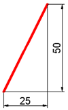
The other common coordinate we use is Cartesian coordinate, by defining X and Y value. We can do this by typing X,Y when dynamic input is asking for next point. After we press comma, then the dynamic input will show you X and Y value like this.

25,50 means 25 units to the right, then 50 units to the top.

If you type positive value, then the next point will be to X/Y positive axis. But if you type negative value, it will be to negative axis FROM your last point. Try it!
Global Coordinate
If you work in land surveying industry, then you will need what we call global coordinate. You may want to precisely draw points or objects from a benchmark point. The intersection point of AutoCAD X and Y axis is the 0,0 coordinate.
Remember: by default positive X axis is to the right, and positive Y to the top.

We can input global coordinate by add prefix hash tag # before typing the XY value. If you add the # prefix, then AutoCAD will ignore the previous point, and measure your point from AutoCAD global 0,0 coordinate. Give it a try!
Using AutoCAD ‘Classic’ Input
All the above input mode is if you have the dynamic input turned on. If you turn it off, then inputting coordinate is slightly different. You will probably see many veteran AutoCAD users still using this way. The main reason people don’t like using dynamic input is because they feel it’s disturbing their view.
If you turn dynamic input off then:
- When you type X,Y value, you are defining global coordinate.
- To define relative coordinate you need to add prefix @ before typing X, Y. It will be @X,Y.
- It also applies to polar coordinate. You have to type @distance<angle for relative coordinate.
It is up to you which one you will use. However, I recommend you to use dynamic input because it is the common way to define coordinate in other CAD applications.
We will have some exercise next.


hello, I have plot my drawing in autocad to pdf. I’m pretty sure that the step to plot is correct. but when I print the pdf, the dimension isn’t precise.
i put the scale 1:100, but when I measure it with ruler, it missed 2 mm.
for example, I draw a line 4000 mm on autocad, and I put the scale 1:100 when plotting. but when I measure with ruler, it just measured 38 mm. how could this possibly happen?
You might need to check the PDF printing scale. By default, it often set to fit the page size.
hi frnd
i m very happy to
learn from u
ur tuition is brilliant
thanksa lot
wish u a happy new year
i want to know how to insert excel file into autocad
And want to know how to start bench mark in autocad
Very useful! thanks.
my educational version defaults all dynamic inputs to 0,0. I enter in 5,10. When I hit enter it places the first point at the x/y axis. What am I doing wrong?
Can you elaborate with the steps you do?
What happen if you use @5,10 instead of 5,10? Does it work as expected?
please i will like to know ow to import coordinate from note pad into AutoCAD 2010 VERSION
Makes no sense!!!