I had a very interesting Revit family sample last week. It is a furniture family, but we can place it just like placing walls: we define first and last point, not by the furniture location. It is not possible to create such a family type using the furniture template. We need to create it using Metric Generic Model line based.rft.
Let us create a new Revit family using that template.
Creating Line Based Family
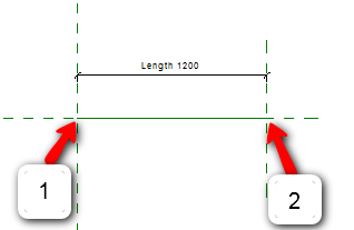
This family has a predefined parameter: Length. It also has two vertical work plane: Left and Right. The work planes intersection points with the center (front/back) work plane are the points you need to define when placing it within a project.
Let us try it. Open right elevation view. Create a profile like below. You don’t need to create the exactly the same profile. Just make it 500mm wide, and create 2nd profile 760mm above the level plane.
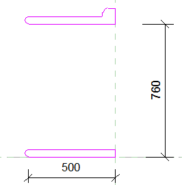
Click extrusion properties on your Revit ribbon, contextual tab. Find extrusion end parameter, and click the small button next to the value.

Find Length parameter, select it and click OK. Click finish extrusion.
We have done! Save this Revit family as ‘base cabinet’. Load it to a project and try to place it.
Hint: If you don’t have floor (or other faces) then you need to change the placement reference to ‘Place on Work Plane’.
Just like placing walls isn’t it?
Using Nested Family
That was fun, but we can do more. We want to fill the gap between base and top panel with typical cabinet units.
Download this file, load this typical unit to base cabinet family.
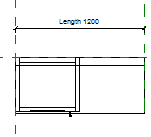
You should see it in 3D like this.
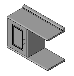
This is a Revit family inside a Revit family definition… or nested family.
Using Array and Formula in Parameters
Creating Array
The next thing we need to do is to multiply the typical unit to match the cabinet length. Open the floor plan view.
Select the typical unit family, and click array on your Revit ribbon.

Place the array like below. After you place it, select the array number.
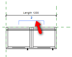
Creating Number of Array Parameter
In option bar, click the drop down label selection.
![]()
Select <Add Parameter…>.
In opened dialog box, type the parameter name, and change the parameter type to instance.
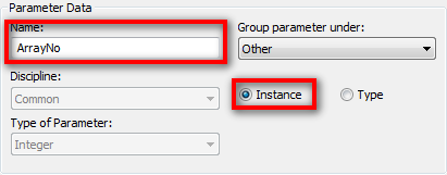
Click OK.
Creating Formula for Array Parameter
Now we need to create a formula, so the number of array will adjust to the cabinet length. Click types from Revit Ribbon.
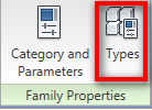
In the family types dialog, find the parameter we created before. In formula field, type Length/600. Remember, formula in Revit is case sensitive!
![]()
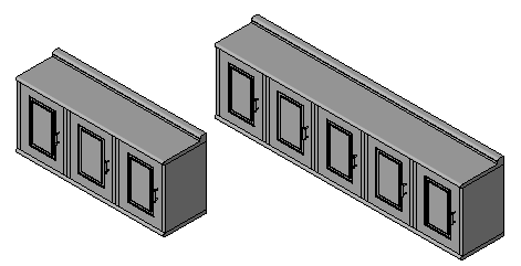
Click OK. Try to reload this family to your project. And try to place it again. Now the number of typical unit will adjust to the cabinet length.
Limitation
This may looks fun and very easy to use. However, there are some limitation to consider:
- I would not recommend you to use this trick if you need to report the family in your schedule. Revit will only recognize the furniture family and types, but it will not report the length or number of typical units in your cabinet. So if you want to report the family in a schedule, use furniture template and define the family types. Use this trick if the family is only for visualization purpose!
- You need to know the typical unit size so you can precisely define the cabinet length. It will not cause error in Revit, but you will see the base and top panel too long or too short if you don’t define its length correctly. Use incremental value 600 for this sample.


Hi Edwin,
The “Typical unit.rfa” file fails to open after downloading. Just letting you know if you want to rectify it. Otherwise, thanks for the tutorial.
Cheers.
Nice article! I have same concept, I used Linear slot diffuser, trench drain and specially adaptive curve trench and SLD.
Hai Edwin,
My Name is Binu Mathew from Kuwait, i used to visit your website and i take this opportunity to congratulate you for your support to the CAD community as a volunteerly, iam lso having a yahoo group called surf2cad (http://tech.groups.yahoo.com/group/surf2cad) try to be a memebr also in that group and help the community,
i switched to Revit MEP 2010 and we are having a cad user group in Kuwait, i atteneded AU 2008 and this year attended only Virtual, Good luck for your hard work
Best regards
Binu Mathew
from Kuwait